To turn on an electrical switch, you typically perform the following steps:
1. Locate the switch: Identify the physical switch that controls the flow of electricity to the device or circuit you want to turn on. Switches can be found on walls, power strips, or directly on the device itself.
2. Check the switch position: Determine the current position of the switch. If it's a toggle switch, it may have two positions: up and down, indicating on and off, respectively. For a push-button or rocker switch, you may need to press or toggle it to the "on" position.
3. Flip or press the switch: Depending on the type of switch, either flip it up or down, press it, or toggle it to the "on" position. This completes the circuit and allows electricity to flow.
4. Verify power supply: After switching on the device or circuit, check if power is being supplied correctly. Look for indicators such as lights turning on or the device functioning as expected.
Remember, always exercise caution when working with electricity. If you are unsure or unfamiliar with the electrical system, it's best to consult a qualified electrician for assistance.
Switch_off
To switch off an electric circuit, you typically need to interrupt the flow of electricity by opening or breaking the circuit. Here are a few common methods to switch off an electric circuit:
1. Toggle Switch: A toggle switch is a lever or button that can be flipped or pushed to open or close a circuit. Flipping the switch to the "off" position breaks the circuit and stops the flow of electricity.
2. Circuit Breaker: Circuit breakers are protective devices designed to automatically switch off a circuit when there is an electrical fault or overload. If a circuit breaker trips, you can reset it by flipping it to the "off" position and then back to the "on" position.
3. Wall Switch: Wall switches are commonly used to control the flow of electricity to lights or outlets in buildings. Toggling the wall switch to the "off" position interrupts the circuit, cutting off power to the connected device.
4. Unplugging: For devices that are powered by a plug, such as lamps, appliances, or electronic devices, simply unplugging them from the power source will switch off the circuit.
It's important to note that when dealing with electrical circuits, safety precautions should always be followed. If you're unsure or uncomfortable handling electrical components, it's best to consult a qualified electrician.
Battery
To switch off an electric circuit powered by a battery, you can simply disconnect the battery from the circuit. Here's how you can do it:
1. Identify the battery: Locate the battery within the circuit. Batteries are typically housed in a battery holder or compartment, or they may be connected directly to the circuit.
2. Disconnect the battery: Depending on the type of battery and its connection, you may need to follow different steps to disconnect it:
- If the battery is connected through wires: Remove the wires from the battery terminals by loosening the screws or clips that hold them in place. Be careful not to touch the exposed ends of the wires together or any other conductive material to avoid creating a short circuit.
- If the battery is connected with a plug: Some battery-powered devices have batteries that can be easily removed by unplugging them from the circuit.
3. Confirm disconnection: Once you have disconnected the battery, make sure that there is no electrical contact between the battery terminals and the circuit. Verify that the circuit is no longer receiving power by checking if any lights, displays, or other indicators are turned off.
Remember, when working with batteries or electrical circuits, it's important to prioritize safety. Take precautions to prevent accidental short circuits or electrical shocks, and if you're unsure about any aspect of the process, seek guidance from a qualified professional.
Motor
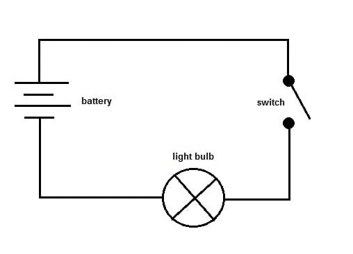
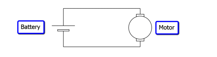
An electric circuit powering a motor typically consists of a power source (such as a battery or electrical outlet), wires, a switch, and the motor itself. Here's a general overview of how the circuit operates:
1. Power source: The circuit requires a source of electrical energy to operate the motor. This can be a battery or an electrical outlet connected to the main power supply.
2. Wires: Conductive wires are used to connect the various components of the circuit. They provide a path for the flow of electricity from the power source to the motor.
3. Switch: A switch is used to control the flow of electricity in the circuit. When the switch is closed or turned on, it allows current to flow through the circuit and power the motor. When the switch is open or turned off, the circuit is interrupted, and the motor stops receiving power.
4. Motor: The motor is the primary component that converts electrical energy into mechanical motion. It typically consists of coils, magnets, and a rotor. When electricity flows through the motor's coils, it creates a magnetic field that interacts with the magnets and causes the rotor to rotate, generating mechanical work.
To switch off the motor in an electric circuit, you would need to open the circuit by turning off the switch or disconnecting the power source, effectively cutting off the flow of electricity to the motor. This will cause the motor to stop operating.
Cell
An electric circuit powered by a cell (or battery) follows a similar principle to other types of circuits. Here's a basic explanation of how an electric circuit with a cell works:
1. Cell (Battery): A cell, or battery, is a device that generates electrical energy through chemical reactions. It typically has two terminals, a positive (+) terminal and a negative (-) terminal. The chemical reactions within the cell create a voltage potential between these terminals.
2. Wires: Conductive wires are used to create a complete pathway for the flow of electricity from the cell to the connected components in the circuit.
3. Load: The load in the circuit refers to the device or component that utilizes the electrical energy to perform a specific function. It could be a light bulb, motor, resistor, or any other electrical device.
4. Switch: A switch is used to control the flow of electricity within the circuit. When the switch is closed or turned on, it completes the circuit, allowing electricity to flow from the cell to the load. When the switch is open or turned off, the circuit is broken, and electricity ceases to flow.
5. Circuit Completion: To create a complete circuit, connect one terminal of the cell to one end of the load using a wire. Then, connect the other terminal of the cell to the remaining end of the load using another wire. This allows the current to flow from the cell, through the load, and back to the cell, completing the circuit.
To switch off the circuit powered by a cell, you can simply open the circuit by opening the switch or disconnecting the wires from the cell terminals. This interruption breaks the flow of electricity, and the load will no longer receive power from the cell.
LED
An electric circuit powering an LED (Light Emitting Diode) follows a similar principle to other types of circuits. Here's a basic explanation of how an electric circuit with an LED works:
1. Power source: The circuit requires a source of electrical energy to power the LED. This can be a battery, a power supply, or any other suitable power source.
2. Wires: Conductive wires are used to create a complete pathway for the flow of electricity from the power source to the LED. They connect the various components of the circuit.
3. Resistor: In most cases, an LED circuit includes a current-limiting resistor. The resistor is connected in series with the LED to regulate the amount of current flowing through it. LEDs have specific voltage and current requirements, and the resistor helps protect the LED from excessive current that could damage it.
4. LED: The LED is a semiconductor device that emits light when current passes through it. LEDs have two leads, a longer one (anode) and a shorter one (cathode). The anode is typically connected to the positive terminal of the power source, while the cathode is connected to the negative terminal.
5. Switch: A switch is used to control the flow of electricity in the circuit. When the switch is closed or turned on, it allows current to flow from the power source, through the resistor, and into the LED. When the switch is open or turned off, the circuit is interrupted, and the LED stops receiving power.
To operate the LED in the electric circuit, you would close or turn on the switch, completing the circuit and allowing current to flow from the power source through the resistor and into the LED. The LED will then emit light. To switch off the LED, you would open or turn off the switch, breaking the circuit and cutting off the flow of current. As a result, the LED will stop emitting light.
Lamp
An electric circuit powering a lamp typically consists of a power source, conductive wires, a switch, and the lamp itself. Here's a general overview of how the circuit operates:
1. Power source: The circuit requires a source of electrical energy to power the lamp. This can be a battery, a wall outlet connected to the main power supply, or any other suitable power source.
2. Wires: Conductive wires are used to create a complete pathway for the flow of electricity from the power source to the lamp. They connect the various components of the circuit.
3. Switch: A switch is used to control the flow of electricity in the circuit. When the switch is closed or turned on, it allows current to flow from the power source to the lamp. When the switch is open or turned off, the circuit is interrupted, and the lamp stops receiving power.
4. Lamp: The lamp, in this case, refers to a light bulb or any other lighting device. When electricity flows through the lamp, it energizes a filament or another mechanism within the bulb, producing light.
To operate the lamp in the electric circuit, you would close or turn on the switch, completing the circuit and allowing electricity to flow from the power source through the wires and into the lamp. The lamp will then illuminate. To switch off the lamp, you would open or turn off the switch, breaking the circuit and cutting off the flow of electricity. As a result, the lamp will turn off.
Fuse
An electric circuit fuse is a protective device designed to protect electrical circuits from excessive current. Here's an explanation of how a fuse works in an electric circuit:
1. Purpose: The primary purpose of a fuse is to prevent damage to the electrical circuit and its components by interrupting the flow of current in the event of a fault or overload. It acts as a safety measure to protect against electrical fires or damage to equipment.
2. Construction: A fuse consists of a metal conductor or wire with a low melting point. It is typically enclosed in a fuse holder. The fuse is connected in series with the circuit it is protecting.
3. Current Rating: Each fuse has a specific current rating, which represents the maximum amount of current it can safely handle. If the current flowing through the circuit exceeds the rated value, the fuse will open or "blow."
4. Operation: When the current in the circuit exceeds the fuse's current rating, the heat generated causes the fuse wire to melt, breaking the circuit and stopping the flow of current. This action protects the circuit and connected devices from further damage.
5. Replacement: Once a fuse blows, it needs to be replaced. Fuses are designed to be easily replaceable, and they come in different types and sizes. It's important to replace a blown fuse with one that has the same current rating to ensure proper protection.
Fuses are an essential component of electrical circuits, particularly in residential and industrial applications. They provide a level of safety by preventing excessive current flow, and they can be used in combination with other protective devices like circuit breakers for enhanced protection.